Making An Electric Motor
By Mike on Saturday, October 23, 2010, 20:02 - Permalink
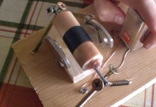 "Dad, I'm bored! What can we do?"
"OK, let's make something, how about an electric motor...?"
So here's how to make a very simple electric motor out of odds and ends:
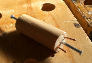 This part is called the rotor - because it's the part that will (hopefully) rotate.
It's made from a section of thick wooden dowel. Into the centre of each end, I've driven a masonry nail (any straight, smooth-surfaced nail or pin will do).
Also at one end, I've tapped in a couple of copper-plated panel pins - these will form part of the commutator (more on that in a moment).
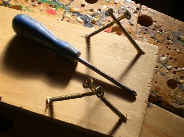 To make the bearings on which the rotor will spin, I drove two pairs of long screws into a piece of scrap timber, angling the screws to cross each other near the heads.
The distance between the two pairs of screws is calculated to be just a bit shorter than the length of the rotor spindle formed by the heads of the two masonry nails.
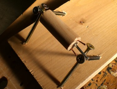 Testing the rotor in place, it's just right - the heads of the nails only just overlap the shafts of the crossed screws, thus allowing it to rotate in place, but preventing it from moving back and forth along its axis.
Minor adjustments at this stage can be effected by just tapping the nails in a little further into the rotor body, or carefully bending the screws a little.
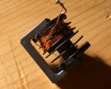 Next, we'll need some wire. I'm using some that I reclaimed from an inductor component scavenged from a broken printer. It's about half a millimetre in diameter and is insulated with varnish or lacquer.
For the electrical connections later on, this insulation will need to be scraped off the ends of the wire using some abrasive paper.
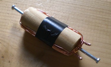 I put about 20 turns of the wire lengthways (all in the same direction) around the rotor body, then scraped off the insulation (just on the ends) and wrapped them around the copper pins.
I happen to own an electronic multimeter, so I took this opportunity to make sure that there was good electrical continuity between the two copper pins. This isn't strictly necessary, but it saves troubleshooting later.
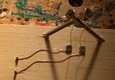 Next, I made the motor brushes - these will make light contact with the copper pins to transfer current to the rotor coil.
They're made from the same wire as the rotor coils - stripped of all their insulation by pulling the wire through a folded sheet of abrasive several times.
They're each secured to the baseboard by wrapping twice around a flat-headed screw, then fastening it down. They can then be pulled taut to straighten them.
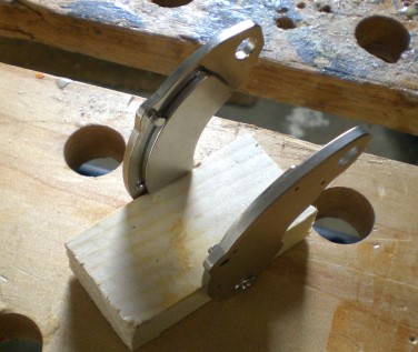 Next, I constructed the stator (the part of the motor that remains stationary) out of a pair of very powerful permanent magnets reclaimed from computer hard drive.
These magnets are permanently fixed to a metal plate and are made with the north and south poles at the opposite ends of their crescent shape.
I screwed them to the sides of a scrap of timber so that they were spaced just a little wider than the rotor. They are arranged with opposite magnetic poles facing each other - that is, without being affixed to the wood, they would attract each other and stick together in this orientation.
The stronger the magnets you can use here, the more likely it is that the motor will work properly, but watch your fingers - the rare earth magnets you can scavenge from hard drives are so strong that they can easily snap together quite violently, pinching skin and causing blood blisters.
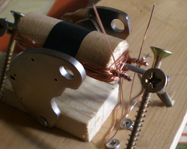 I tested the stator in place, making sure that the rotor would turn, then screwed it down to the baseboard.
(Note that the magnets are positioned so that the poles at one end of each are positioned at a height approximately level with the middle of the rotor.)
And that's it - the motor is ready to configure and test. Configuration largely consists of tweaking the wire brushes so that they make contact against the copper pins (as in this photo) without restricting the rotation of the spindle.
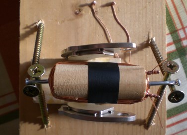 Here's the motor ready for testing, viewed from above.
To make it easier to test the operation, I've brought the other ends of the brush wires out and connected them (after stripping the ends) to another pair of copper pins - this way, a PP3 battery can just be pressed against them, leaving the other hand free to effect any small adjustments.
And it works! - with just a little adjustment to the brushes, it spins freely and continuously. A little dab of oil (vegetable oil works fine) on the ends of the spindle - where they contact the bearing - makes it run even faster.
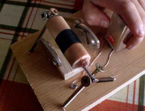
Electric Motor Theory
OK, so how does it work?
The simple explanation is that when the brushes are in contact with the commutator pins on the rotor, electric current is flowing through the coil, this generates a magnetic field which interacts with the permanent magnets in such a way as to turn the rotor.
This rotation does break the electrical circuit, but the rotor has momentum and continues to turn until it brings the brushes back into contact with the commutator pins again, completing the circuit and generating more rotary forces again, in the same direction.
OK, But WHY Does It Work
Well, it's actually pretty complicated and involves some interesting physics to do with magnetic fields around a conductor that can be thought of as circulating in a clockwise direction when viewed in the direction of the flowing current, like this:
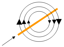 When this happens within another magnetic field, the conductor experiences a sideways force perpendicular to the field - crucially, in the motor, because the coil is wrapped around both sides, the forces being experienced on each side are in opposite directions. Furthermore, the force is multiplied by the multiple turns of wire on the rotor.
I realise that's still an absurdly simplified and perhaps not even entirely accurate explanation, but it'll have to do.
Further reading on the topic of magnetic fields and forces is widely available, if this project has left you hungry for knowledge.
Video
Video of this motor in operation:
Note
Before, during or after the video(s) embedded in this page, the player may display advertisements or links to additional videos - these are not affiliated to Atomic Shrimp and the selection is something over which I have no control.
