Making A Stirling Engine
By Mike on Sunday, November 11, 2012, 22:49 - Permalink
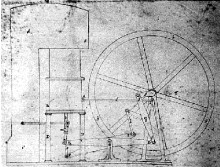 This is a project to try to make a small working model Stirling engine - designed to run off a small heat source such as a candle or cup of hot water.
Stirling Engine Theory
In a nutshell, a Stirling engine works like this:
1. The air in a chamber heats up and expands, pushing out the power piston (green), rotating the crankshaft
2. The crankshaft pushes the displacer piston (blue) toward the hot end of the chamber - moving the hot air toward the cold end.
3. The air in the chamber cools, contracting, reducing the pressure inside (including the pressure behind the power piston.
4. The reduced pressure permits atmospheric pressure (outside) to push the power piston back in - but by this time, the shaft has rotated far enough that the motion completes the revolution.
5. Meanwhile, the displacer piston has returned to the cold end, moving the air back toward the hot end.
The Basic Design (Simplified)
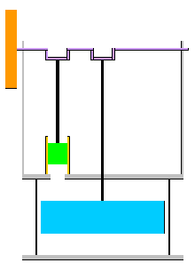 NB: this is a vastly simplified diagram - it doesn't show how the two cranks on the crankshaft are offset from one another by 90 degrees (more on this when I get to that part of the build) - it also omits any hinged parts of the connecting rods.
The chamber
I want to be able to see the displacer piston working, so I decided to make the chamber out of glass - I set about cutting an open-ended cylinder out of a jam jar.
This turned out to be harder than I thought, but I eventually worked out the technique - as demonstrated in this video:
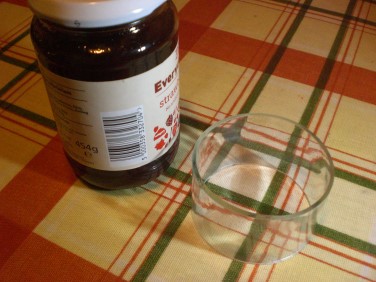 I ended up with a neat cylinder of glass - about 6cm in diameter and 4cm tall.
The displacer piston needs to be a little smaller than half the height of the chamber and smaller in diameter, so it can move freely up and down - a loose fit.
The Displacer Piston
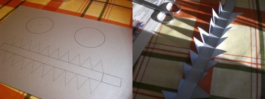 I designed the parts for the displacer piston on my computer - calculating the circumference from the desired diameter (multiplying the diameter by Pi).
I printed out the parts on some thickish silver-grey paper.
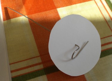 To strengthen the displacer, I also cut out a couple of discs of thicker card.
The connecting rod (a straightened paper clip) will pass through the centre - the circumference band will be attached to this card disc, then another paper disc goes on top.
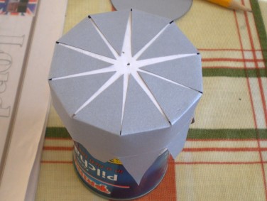 I supported the card disc on a small food can and attached the tabs of the circumference band, aiming their points toward the centre, to keep everything neat and symmetrical.
After this glue had set, I pushed in the connecting rod and stuck the circle of silver card on top, to secure the rod in place.
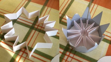 To strengthen the structure of the piston, I cut a strip of card - the same height as the piston, folded into a concertina and glued the ends in a loop.
I ran a line of glue around the inside bottom of the piston, then dropped the zigzag support piece inside, then placed the second card disc on top (again, with a circle of glue to stick it to the structural support.
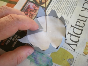 Supported by the internal structure it was easy to stick down the tabs to the white card.
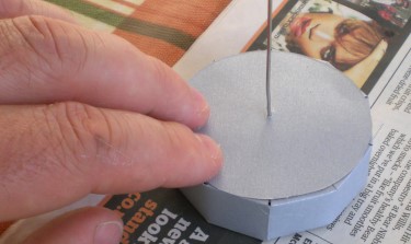 I then added the second circle of silver card and the displacer piston was complete.
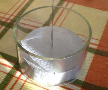 I tested the piston inside the chamber - a perfect fit - it moves freely up and down with a little gap around the edges.
When it's pushed up and down, the air passes around it and moves to the other end of the chamber.
The Bottom Plate
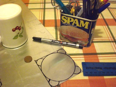 Using mugs and coins as circle guides, I drew out a pattern for the bottom plate on a sheet of 2mm Aluminium.
The 'ears' at each corner will be drilled so that the plate can be bolted to a similar one at the top, with the chamber sandwiched in between.
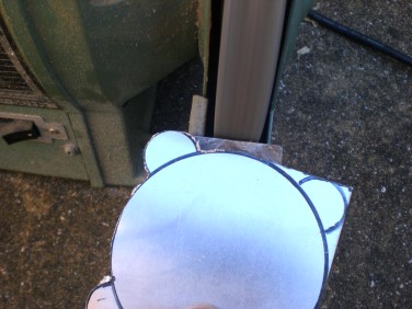 I cut around it with a hacksaw, then ground away the unwanted sections with a bench grinder.
This left some horrible burrs on the edges.
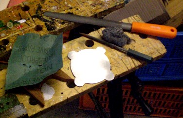 With the application of files, wet and dry abrasive, steel wool and a good deal of elbow grease, I removed all the sharp edges.
The flat surfaces had a few scratches on them too, so I polished these to a nice brushed finish with the steel wool, in a careful circular motion.
The Power Piston And Cylinder
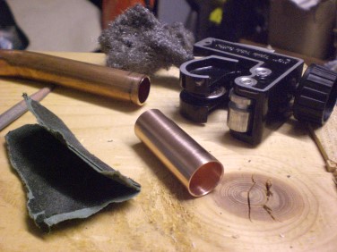 The cylinder for the power piston is a 4cm section of 15mm domestic plumbing pipe.
The pipe cutter tool creates a slightly crimped flange on the cut end, so I carefully filed this away, then sanded the end and cleaned up the outside with steel wool.
 The piston itself was tricky to work out - I needed something that snugly fits the inside diameter of the tube - I've seen others solve this by using a section of smaller tube, plugging the end with solder, but I couldn't find anything suitable.
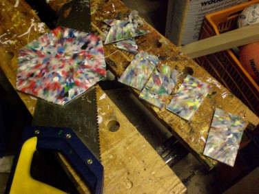
Then I hit on an idea - I have loads of leftover recycled HDPE plastic from my abortive recycled plastic boat project. This material should make a good piston, if it can be made the right shape.
I cut some rectangular pieces of the HDPE material and heated them up in my sandwich toaster, until they were sticky and pliable.
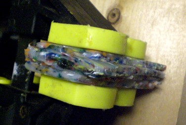 I pressed the pieces together into a single rough block.
I then clamped this overnight.
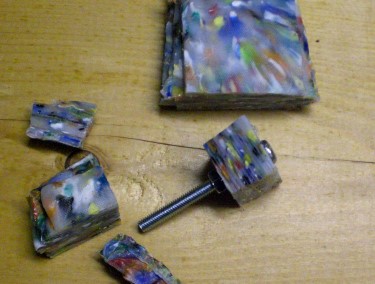 I cut a section from the block and drilled it, then mounted it on a bolt.
I'll set this in an electric drill and machine it down to a cylinder of the right diameter - a bit like woodturning.
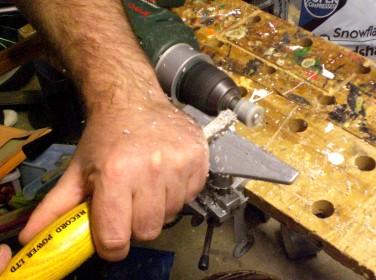 I'm not sure whether to call this machining or turning.
The latter, I guess, as this is a small drill - powered woodturning lathe and I'm using woodturning tools and technique.
I rounded off the workpiece to a cylinder and slowly reduced the diameter.
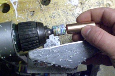 Every now and again, I stopped and offered up the cylinder to try to work out how much more to shave off.
I finished with a strip of abrasive paper.
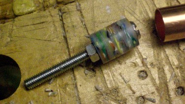 Here's the finished piston - not a bad fit, and the HDPE material slips very nicely against the smooth inside wall of the copper pipe, without the need for any additional lubrication.
However, I think I made it just a little too small, as there is a little too much lateral wiggle - so I'm making this piece over again - this was good practice though.
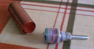 Here's piston MK2 - this time, once I got close to the correct diameter, I put down the turning gouge and brought it down it its final size using only abrasives.
This resulted in a piston that's very nice and smooth, and fits the inside of the pipe snugly, but still moves freely up and down.
The Flywheel
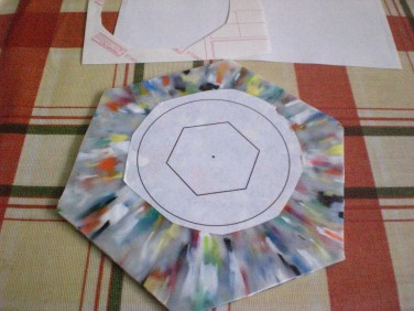 The flywheel is to be made out of a sheet of recycled HDPE plastic that I made when I was trying to construct a recycled plastic boat.
I printed a pattern for the flywheel onto a sticky label and fixed it in place.
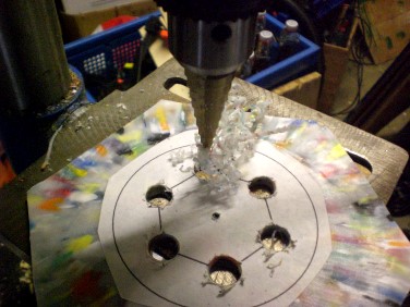 I drilled a central hole, surrounded by six equally-spaced larger ones - these are mostly for decorative effect.
I roughly cut out the wheel (leaving a margin of spare material), then mounted it on a steel bolt, fastened tight with a nut and star washer, then fitted this into my drill-powered lathe,
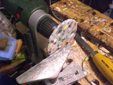 Working the piece in the drill lathe makes it easy to trim everything up so that it's really well-balanced and symmetrical.
I rounded off the rim and smoothed off both faces, adding a few more decorative details such as a dished section and a central boss.
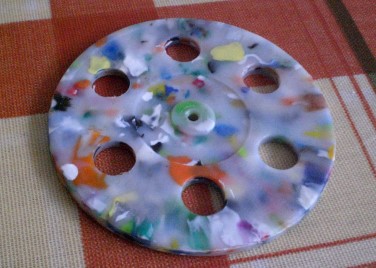 So here's the finished flywheel - I tested it for balance by spinning it on a smooth nail - it's good - spins very cleanly and smoothly.
The Top Plate And Superstructure
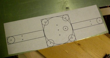 The top plate will have a couple of arms that will be bent upwards to support the crankshaft and other components.
This was all too complex to bodge out by hand like I did with the bottom plate, so I laid everything out using Inkscape, printed it on a sheet of label paper, then stuck it on the metal sheet (on top of a layer of protective film that was already there).
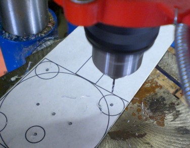 I figured the paper template would probably get messed up during the course of cutting and filing the top plate, so I took this opportunity to drill out pilot holes.
These mark the positions of various screws, apertures etc - I'll drill them out to their proper sizes later.
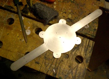 Cutting, filing and finishing of the top plate was a similar job to that of the bottom plate - lots of laborious and careful grinding, filing, deburring, sanding, followed by a final polish with steel wool.
So that's the top plate done. The jobs left after this are the most fiddly, and require the greatest of precision...
The Crankshaft
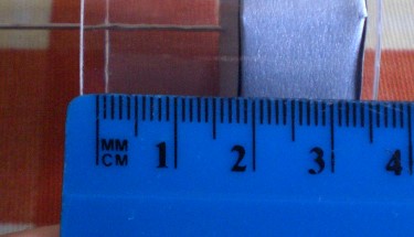 The offset on the cranks needs to be no more than half the maximum travel of the pistons.
In my case, that's half of 20mm - so I'm going to aim for a 9mm crank offset (to allow a little room for error).
For the crankshaft, I needed a nice smooth, straight rod that I would be able to bend at sharp angles.
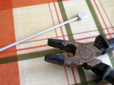 I could have sourced some expensive bit of metal stock for this, but instead, I just picked up an aluminium knitting needle for 25 pence at a charity shop.
I wrapped a couple of turns of electrical tape around the jaws of my pliers, so they would grip the rod without chewing it up.
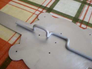 The first attempt was a disaster - the thickness of the metal is about 3mm - and it's not completely easy to control where, in the thickness of it, the bend will be centred
Fortunately, the knitting needle was long enough for another attempt - and this time, after a little practice, it worked fine.
I measured it up against the holes in the top plate - the left one will be the opening at the bottom of the power piston, the right one will be the location of the gland for the displacer piston.
Configuring Holes And Stuff
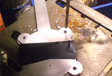 I taped the top and bottom plates together, then drilled through the corner holes together, to ensure that they are in perfect register, and that the bolts which will eventually sandwich this all together will be able to tighten without twisting things out of shape.
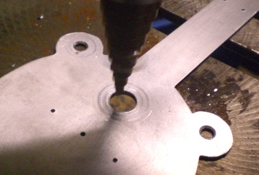 I also drilled out the hole where the power piston will be fitted to 10mm diameter - this is big enough to allow a good flow of pressurised air into the piston, but it still allows enough material for the cylinder to be glued in place.
(I plan to mount the power cylinder on the top plate with epoxy resin).
The Displacer Gland
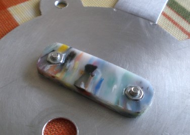 The thin wire on which the displacer piston is mounted needs to enter the main chamber through a hole in the centre of the top plate - but this joint must be as near airtight as possible.
I cut a small piece of recycled HDPE panel - this will be bolted tight to the top plate, then drilled through at exactly the right diameter for the wire.
The HDPE plastic is very slippery, and its slight pliability should provide a partial seal against the wire.
I bolted the displacer gland to the top plate using countersunk head bolts (so they don't intrude into the chamber below. I also drilled a shallow recess in the top of the plastic so the nuts would be captured into it (actually, it was just because the bolts were a little shorter than I'd have liked).
I smeared a very thin layer of silicone sealant onto the underside of the gland piece before attaching it - so there shouldn't be any loss of pressure through the bolt holes.
Finally, I drilled a narrow hole through the gland from the underside, then drilled it halfway through underneath with a larger drill bit - so that the amount of material in contact with the moving displacer piston rod will be minimised.
Connecting Rods
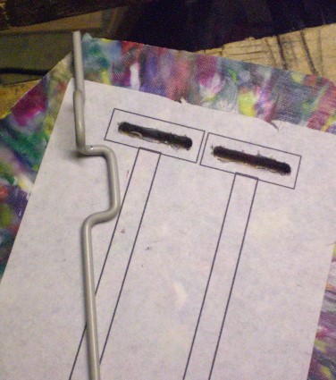 I'm doing something slightly unconventional with the connection between pistons and crankshaft. The normal arrangement would be to have a connecting rod with a bearing at each end, so it would provide a hinged joint that would follow the horizontal component of crankshaft movement at the top end.
Instead, I'm treating the crankshaft as a cam, which will travel inside a slot at the top end of the connecting rod - thus, the connecting rod will only need to travel up and down - in the same axis as the piston. This device is called a Scotch Yoke.
The connecting rod will be made of... you guessed it - recycled HDPE. I printed out the pattern and stuck it on, then cut out with drill and hacksaw.
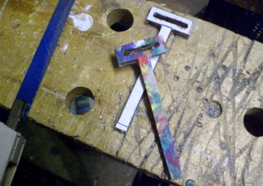 Here they are in the rough - the HDPE material cuts very neatly with an ordinary hacksaw blade - the only real difficulty was holding a fairly small part whilst making the last few cuts - but I managed it in the end.
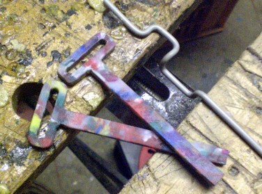 A few minutes work with files and abrasives and the connecting rods are pretty much completed.
I'll need to fashion some kind of bracket to connect one to the top of the power piston.
The connection to the displacer piston should be simpler, as the wire itself can be bent to form the bracket or coupling.
Brackets And Fittings
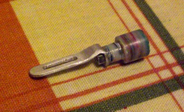 I made a small bracket to attach the top of the piston to the bottom of the connecting rod.
This is slotted, so as to provide a little scope for adjustment.
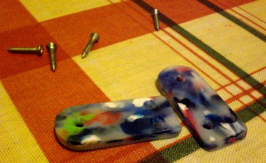 I cut a couple of small pieces of recycled HDPE to make crankshaft bearings.
The axle hole is countersunk on both sides, so that the shaft will be in contact with only a small area of material.
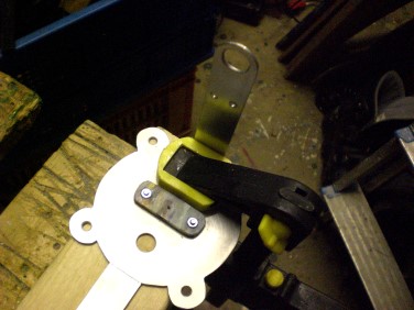 I drilled out the holes in the support arms to fit the axle bearings.
Then it was time to bend up the support arms - I clamped the top plate flat to a piece of scrap wood, then bent each arm up tight against the edge of the clamp jaw.
A Snag
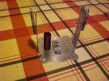 Now I hit a small snag - not bad, considering it's the first one for this project.
I've actually under-estimated the length of the support arms - it had been my intention to screw through the holes attaching the bearings, into a horizontal shelf containing slots which would constrain the connecting rods (preventing them from twisting), but there isn't room.
If I fit it here, it will interfere with the piston at it's top of travel.
Fortunately, there's an easy fix - I'll just make a fresh pair of axle bearings that are longer - and cut off the drilled ends of the support arms.
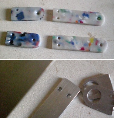 I made some new, taller bearings - actually a bit neater than the first ones.
I also cut off the tops of the bearing supports (gulp - measure twice, cut once).
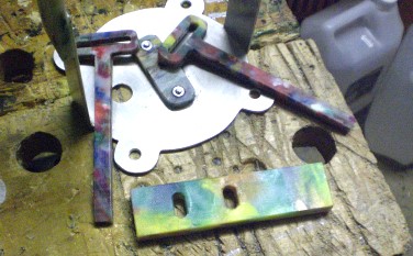 The last component to be made is a sort of horizontal shelf with a couple of slots in it - the connecting rods pass through this and it constrains them to only move in a vertical axis, without twisting.
(This is important - without this, the Scotch yokes would not function).
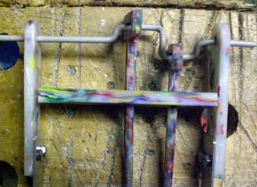 Unfortunately, this last piece didn't quite work out as planned.
Even though I pre-drilled the plastic, it split when I screwed the joints together. I will have to re-make this component - probably out of metal instead.
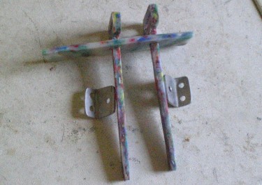 I had to make and remake the constraint bar several times - twice out of thick plastic (the first was a mess, the second split), then I tried a strip of Aluminium (snagged on the connecting rods), then hardwood (not smooth enough to let the connecting rods slip freely).
Finally, I made another out of thin recycled HDPE and I think this is OK. I also had to make a couple of little metal brackets for it though.
Attaching The Power Piston Cylinder
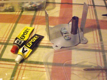 Using a scrap of abrasive, I gently roughed up the bottom end of the power cylinder and also the top plate, around the hole where it will sit - a slightly irregular surface provides greater surface area for glue to grab hold of.
I mixed up some epoxy glue, let it settle into a smooth, flat blob, then dipped the bottom end of the power cylinder into it and placed this carefully onto the plate - sighting down the tube to ensure it was centrally positioned over the hole.
I secured the tube in place with a rubber band while the glue was curing, to prevent any movement and to ensure a tight joint - a thin layer of glue in a joint is usually stronger than a thick one.
I carried out this glued assembly on a flattened plastic bag, where it will be left until set (epoxy glue won't stick to polyethylene).
Configuring the connecting rods
 The connecting rod for the power piston was fairly easy to set up, because of the slotted adjustable bracket I made for it.
The connection to the displacer piston had me stumped for a while - how to attach a thin vertical wire to a vertical plastic stick.
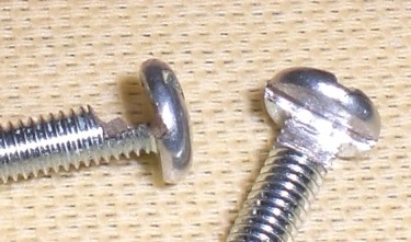
Then I figured it out - I filed halfway through the shaft of a small bolt, just beneath the head, then I used a hacksaw to cut a slot in the underside of the head. When tightened against the wire, this will hook it firmly in place.
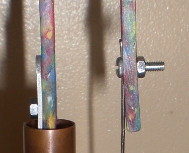 So here's what the two connecting rods look like when fixed together.
As well as the hook-bolt device, the wire shaft for the displacer piston also nestles into a shallow slot engraved into the connecting rod.
Assembly
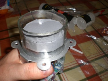 Time to start assembling. I gave both ends of the glass cylinder a thin coat of silicone sealant, then began bolting everything together.
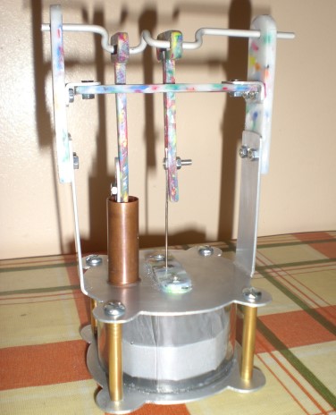 It wasn't easy to get together - I had made some short pieces of brass tube to cover the bolts - partly for aesthetics, but mainly to prevent the bolts being overtightened, cracking the glass. However, these were a really tight fit on the bolts, making assembly really tough.
But it all went together eventually. I do start to wonder if this thing will actually run - the pistons move quite freely when the shaft is turned, but it may be that I've made some of the parts too big and heavy for the amount of power this machine will develop.
I think I will need a larger flywheel - and I reckon it will need balancing weights to offset the weight of the displacer piston and connecting rods.
A Setback
Somehow, I managed to crack the glue joint between the power cylinder and top plate, so I will have to redo this - but hopefully that won't entail disassembly of the chamber itself - I should be able to disconnect and lift away the crankshaft and bearings to work on the power cylinder again.
Fitting The Flywheel And Balancing
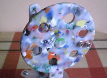 I secured the crankshaft in place by adding washers, then just gluing small nuts onto the ends to serve as stops, preventing the shaft from slipping back and forth through the bearings.
Then I just glued the flywheel in place - hot melt glue doesn't exactly stick to HDPE, but it's sufficiently grippy and rubbery that it secures the wheel on the axle stub.
The wheel is balanced with a couple of heavy screws driven into small holes drilled into the face - these are aligned opposite the midpoint of the two cranks, so they should serve to balance some of the weight of the two pistons.
Testing
Finally! Time to test.
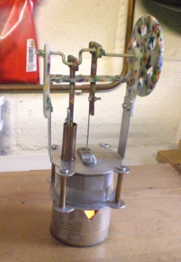 I set the engine on top of a stand made from half a tin can with a lit tealight candle underneath and waited for the bottom plate to heat up.
Despite all efforts though, I was unable to get the engine to run, or even show any inclination to do so.
It isn't sticking anywhere, but maybe it's either losing compression through the displacer gland or power piston itself.
Or maybe I need a hotter heat source - I'm going to try again with an alcohol burner. I'm also going to try to balance the flywheel more finely.
There could still be hope...
Another Try, But Still No Joy
I tried again, replacing the tealight candle with a small pot of alcohol gel, which burned much hotter (so hot in fact that the inside of the chamber filled with smoke), but it was still impossible to get the engine to keep turning over - once or twice it might have shown the tiniest tug of power, but I could just have imagined it.
I wonder if a chamber and piston of this size just isn't big enough to develop enough power to move the mechanical parts of the device.
I'm not going to be deterred though - other people have done this, and the principle is sound even if I couldn't implement it this time. I may start over with another build, on a larger scale, built for power more than appearance.
Note
Before, during or after the video(s) embedded in this page, the player may display advertisements or links to additional videos - these are not affiliated to Atomic Shrimp and the selection is something over which I have no control.
